All calibration documentation issued by Odin Metrology, Inc. contains all information
required by ANSI/NCSL Z540, ISO Guide 25 and ISO 17025. Detailed worksheets with all
data for "as recieved" condition and for "as final" are provided with all calibrations.
Sound level meters are calibrated to the international standard for which they are designed. Older
model sound level meters are generally tested to IEC 60651 (often abbreviated as IEC 651) or
ANSI S1.4. Modern sound level meters are generally tested to IEC 61672. Most sound level meters
have a clear marking on the backside indicating which standard they are designed to fulfull.
|
Sound Level Meters & Calibrators
|
|
Sound level meters with a marking indicating which standard they are designed for are tested
to that standard. Nearly all sound level meters are designed for either IEC 60651/ANSI S1.4
or IEC 61672. Octave band filters are tested to the IEC 61260 standard. The following is a
list of tests performed on sound level meters submitted to Odin Metrology, Inc. Tests without
a section number citations are tests added to the reports by Odin Metrology and are just for
additional information. For each test listed below, click on the test name for a description
of that test.
|
IEC 61672
| Test (click name for test description) |
IEC 61672 Section |
| Sensitivity Verification with Acoustic Calibrator | 3 § 9 |
| A sound level calibrator is mounted on the sound level meter and the internal calibration is started. The SLM indication is recorded before and after calibration. |
| Acoustic Frequency Response with Microphone | 3 § 11 |
| The acoustical frequency response is tested using a multifunction acoustical calibrator type 4226 in C frequency weighting. |
| Self-Generated Noise | 3 § 10 |
| For A-weighting, the noise is measured with the microphone installed and an acoustic chamber on the microphone which eliminates ambient noise. For C- and Z-weighting, the input is terminated with a shorted dummy microphone of equal capacitance. |
| Output Impedance with Shorted Output | 2 § 9.18 |
| When the AC-output on the meter is shorted, the SPL may not change by more than the specified tolerance. |
| AC Full Scale Output Voltage | N/A |
| The sound level meter is set up to indicate full-scale on the display and the AC output is measured. Input frequency is 1,000 Hz. |
| DC Full Scale Output Voltage | N/A |
| The sound level meter is set up to indicate full-scale on the display and the DC output is measured. Input frequency is 1,000 Hz. |
| Reset | 2 § 9.17 |
| It is verified that the display resets after pressing the reset button on the SLM. The initial input level is FSD. |
| Overload Indication | 3 § 18 |
| The first Leq indication of overload at a level higher than FSD-1 dB is recorded for both positive- and negative-one-half-cycle signals at 4.0 kHz. The difference between the two levels may not exceed the specified tolerance. |
| DC Linearity | N/A |
| The sound level meter is set up to indicate full-scale on the display and the DC-output voltage is recorded in decreasing 10-dB steps down to the lower limit of the measuring range. |
| Peak-C Sound Level | 3 § 17 |
| The sound level meter's peak-C response to single one-cycle and positive- and negative-going half-cycle sinusoidal signals is measured. |
| Decay Time Constants for Time Weightings Fast and Slow | 2 § 9.11 |
| The decay rate of the display value on the sound level meter is measured after a steady 4.0 kHz signal is removed. |
| Difference in Indication | 3 § 13 |
| With reference to fast time weighting and A frequency weighting at the SLM reference level, the measurements of all other frequency weighting parameters and all other time weighting parameters may not differ by more than the specified tolerance. |
| Frequency Response | 3 § 12 |
| The SLM's frequency response is recorded by varying the frequency as specified. The reference level is FSD-45 dB at 1.0 kHz. For A-weighting, the test is performed as an "inverse weighted" test during which the display value is held constant by adjusting the input level corresponding to the nominal A frequency weighting curve defined by IEC 61672. IEC 61672 defines this test from 63 Hz to 16 kHz; "N/A" is reported instead of "Fail" for frequencies outside of this range. |
| Single Toneburst Response | 3 § 16 |
| The sound level meter's fast and slow time weighted response to single tonebursts at 4.0 kHz is measured. The baseline input level is FSD-3 dB. For toneburst tests in fast and slow time weightings, the toneburst durations tested are: 1,000, 500, 200, 100, 50, 20, 10, 5, and 2 ms. Toneburst tests in fast time weighting additionally include burst durations of 1, 0.5, and 0.25 ms. |
| SEL Response to Repeated Tonebursts | 1 § 5.9 |
| The sound level meter's sound exposure level (SEL) response to repeated tonebursts at 4.0 kHz is measured. The baseline input level is FSD-3 dB. Toneburst durations tested are: 1,000, 500, 200, 100, 50, 20, 10, 5, 2, 1, 0.5, and 0.25 ms. |
| Level Linearity | 3 § 14, 1 § 5.5.6 |
| Level linearity is tested in A-weighting at 8.0 kHz. Increasing input levels continue up to the first indication of overload. The test is continued with decreasing input levels down to the lower limit or the first indication of underrange. |
IEC 60651/ANSI S1.4
| Test (click name for test description) |
IEC 60651 Section |
ANSI S1.4 Section |
|
| Sensitivity Verification with Acoustic Calibrator | N/A | N/A |
| A sound level calibrator is mounted on the sound level meter and the internal calibration is started. The SLM indication is recorded before and after calibration. |
| Acoustic Frequency Response with Microphone | 5.1, 5.2 | 6.1, 6.2 |
| The acoustic frequency response is tested using a multifunction acoustical calibrator type 4226 in C frequency weighting. |
| Self-Generated Noise | 5.6 | 6.6 |
| To measure inherent noise, the input to the SLM is terminated with a shorted dummy microphone of equal capacitance. |
| Output Impedance | 9.2 | 10.2 |
| A reference signal is applied to the sound level meter and the output is shorted. The indicated level may not be affected by more than the specified tolerance. |
| AC Full Scale Output Voltage | N/A | N/A |
| The sound level meter is set up to indicate full-scale on the display and the AC output is measured. Input frequency is 1,000 Hz. |
| DC Full Scale Output Voltage | N/A | N/A |
| The sound level meter is set up to indicate full-scale on the display and the DC output is measured. Input frequency is 1,000 Hz. |
| DC Linearity | N/A | N/A |
| The sound level meter is set up to indicate full-scale on the display and the DC-output voltage is recorded in decreasing 10-dB steps. |
| Overload Indication | 8.3.1 | 9.3.1 |
| SLM overload is expected when the display value exceeds the tolerance of the inverse A-weighted test (an overload indication when overload is not expected is not a failure condition). |
| Peak Characteristic | 6.5 | 7.5 |
| The rise time of the peak detector must be such that the response of a 100 µs rectangular half-cycle pulse is similar to that of a reference half-cycle pulse of 10 ms. |
| Decay Time Constants | 6.2, 6.3 | 7.2, 7.3 |
| The decay rate of the display value on the sound level meter is measured after a steady 4.0 kHz signal is removed. |
| Steady-State Response | 6.4 | 7.4 |
| With reference to A-frequency-weighting and fast time-weighting at the SLM reference level, the measurements of the other time weighting parameters may not differ by more than the specified tolerance. Test frequency is 1.0 kHz. |
| Frequency Response | 5.1, 5.2 | 6.1, 6.2 |
| The sound level meter's frequency response relative to the meter's reference level at 1,000 Hz is recorded by varying the frequency as specified. |
| Toneburst Response | 6.2, 6.3 | 6.2, 6.3 |
| The sound level meter's A-weighted response to tonebursts at 2.0 kHz is measured. Toneburst tests include: fast time weighting with single tonebursts, slow time weighting with single tonebursts, impulse time weighting with single tonebursts, and impulse time weighting with continuous tonebursts. All tests are performed at input levels of FSD-4 dB and each input level in decreasing 10 dB steps given that the level is within the SLM's measuring range. For fast time weighting, the tonebursts have a duration of 200 ms. For slow time weighting, the tonebursts have a duration of 500 ms. For impulse time weighting with single tonebursts, the meter is tested with tonebursts of durations 2, 5, and 20 ms. For impulse time weighting with continuous tonebursts, the meter is tested with 5 ms duration tonebursts with repetition rates of 2, 20, and 100 Hz. |
| Differential Level Linearity | 6.9, 6.10 | 7.9, 7.10 |
| Level linearity is tested at 1.0 kHz. The input level is varied precisely and the indicated level on the display must correspond with the change of input level. Test is performed in A- and C-frequency weighting. |
IEC 61260 (octave band filters)
| Test (click name for test description) |
IEC 61260 Section |
|
| Level Verification of Filter+SLM | N/A |
| Relative to 94 dB at 1,000 Hz, it is verified that for each filter center frequency, if the input frequency matches that of the center frequency, the meter should indicate within the specified tolerance. |
| Filter Check | N/A |
| At each center frequency, frequencies equaling the center frequency plus and minus 1/6 octave for 1/3 octave bandwidth or 1/2 octave for 1/1 octave bandwidth shall cause the filter to respond with attenuation within the specified limits. |
| Relative Attenuation | 5.3 |
| The attenuation of the filter at the specified frequencies shall be within the specified tolerance. The frequencies are calculated as octaves from the center frequency. The factors defined by IEC 61260 (Table 1) are: ±4, ±3, ±2, ±1, ±1/2, ±3/8, ±1/4, ±1/8 and 0 octaves. |
|
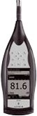
Brüel & Kjær 2250/2270 sound level meters
(IEC 61672)
|
Reports for the Brüel & Kjær sound level analyzer type 2250, and variants
2250 Light and 2270, contain data for the SLM and the octave filters, if available. For
2270, data is supplied (both SLM and filter data) for each of the two channels. The
filter report includes data about linearity and band edge responses. Odin Metrology will supply a
limited filter report containing data for a single 1/1-octave filter.
View example 2250 report (including "limited" filter report) (PDF)
|
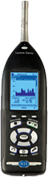

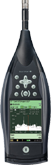
Larson Davis LxT/831 sound level meters
(IEC 61672)
|
Reports for the Larson Davis sound level meter type 831 contain data for the SLM and
the octave filters, if a license for installed. The filter report includes data about
linearity and band edge responses. Odin Metrology will supply a limited filter report
containing data for a single 1/1-octave filter.
View example 831 report (including "limited" filter report) (PDF)
|
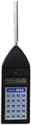

Larson Davis 812/820 sound level meters
(IEC 60651)
|
A report for a Larson Davis type 812 or 820 sound level meter consists of 9 pages
of data including extensive toneburst testing as per IEC 60651. Other tests include
differential level linearity, frequency responses for A and C frequency weighting,
and test of overload detector functionality.
View example 820 report (PDF)
|
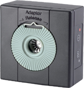
Brüel & Kjær 4231 acoustic calibrator
|
A certificate for a 4231 calibrator contains data before and after any adjustments
were made. Data includes sound pressure level (at both 94 and 114 dB ranges),
frequency, and distortion measurements.
View example 4231 report (PDF)
|
|
Condenser Microphones & Ear Simulators
|
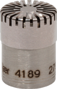
Brüel & Kjær 4189 ½" condenser microphone
|
Microphone calibrations are documented with a three page certificate containing all
necessary details. The third page contains 1/3 octave tabulations for the microphone's
frequency response: actuator, pressure (if applicable), 90 degree incidence, free field
and random. Upon request, the electronic data can be delivered to the customer in
Microsoft Excel format for use in correcting data obtained, for example, from a
Brüel & Kjær PULSE system.
View example microphone certificate (PDF)
|
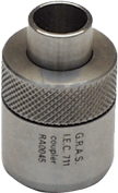
GRAS Ear Simulator RA0045
(IEC 60711)
|
Similar to microphones, ear simulators are documented with a three page certificate
containing all necessary details. The third page contains the simulator's frequency
response. Upon request, the electronic data can be delivered to the customer in
Microsoft Excel format for use in correcting data obtained using the simulator.
View example RA0045 certificate (PDF)
|
|
Accelerometers & Vibration
|
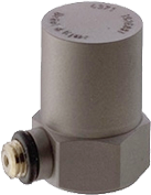
Brüel & Kjær 4371 single-axis accelerometer
|
Accelerometer calibrations are documented with a two- or three-page certificate.
Pages one and two contain the calibration information as obtained by the Brüel
& Kjær transducer calibration system type 9610 and technical data about 9610.
Page three contains an optional mounted resonance plot.
View example single-axis accelerometer certificate (PDF)
|
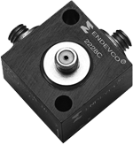
Endevco 2228C triaxial accelerometer
|
Triaxial accelerometer calibration is documented with a two-page certificate
containing the calibration information as obtained by the Brüel & Kjær transducer
calibration system type 9610 and technical data about 9610.
View example triaxial accelerometer certificate (PDF)
|
Brüel & Kjær 2133 analyzer
|
|